XR4 to XR3 Conversion Neck Assembly
This kit provides a Neck Assembly to convert a RealPOS XR4 to RealPOS XR3. The Neck Assembly can support any of the following displays:
•10.1” XL10W Display (5910)
•15” XL15 Display (5915)
•15.6” XL15W Display (5916)
•10.4” X-Series Display (5968)
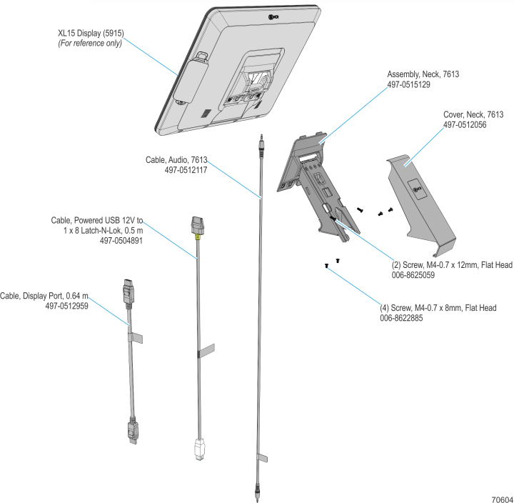
Kit Contents
Installation Procedure
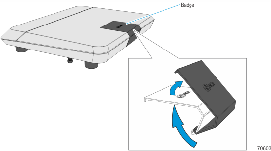
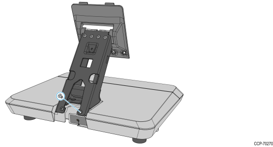
1.Push the Badge firmly from underneath the Base until it gets unhooked.
2.Mount and position the Neck Assembly on the Base.
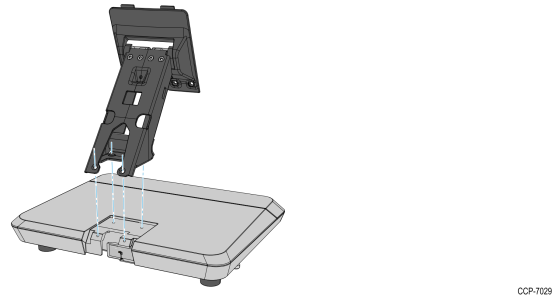
3.Mount and partially tighten a screw on one of the outside mounting holes.
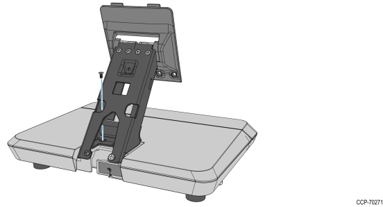
4.Mount and partially tighten a second screw on the inside mounting hole diagonally opposite to the mounted screw.
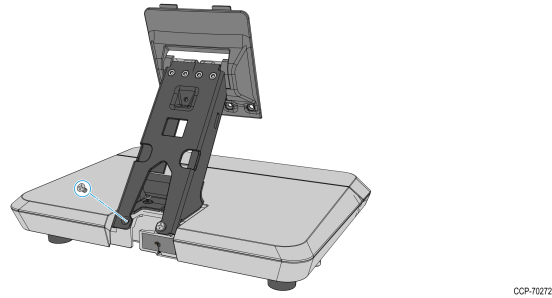
5.Mount and partially tighten the third screw on the second outer mounting hole.
6.Mount and fully tighten the fourth screw on the second inner mounting hole.
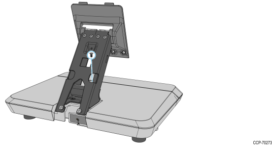
7.Fully tighten the three screws.
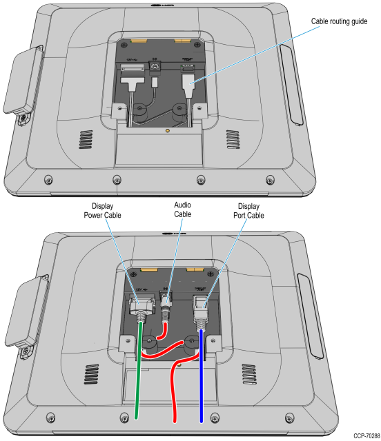
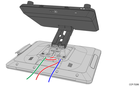
8.Connect the Display cables and route them according to the imprinted routing guide.
a.Connect and route the Audio Cable first. Route the cable looping around the cable guides as shown.
b.Connect the Display Power cable and route straight down over the audio cable.
c.Connect the Display Port cable and route straight down over the audio cable.
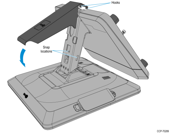
9.Mount the Neck and Base assembly on the Head assembly.
a.Insert the tabs on the Display Mounting Bracket to the slots on the rear of the Head Assembly and then slowly rotate the Neck and Base assembly downward.
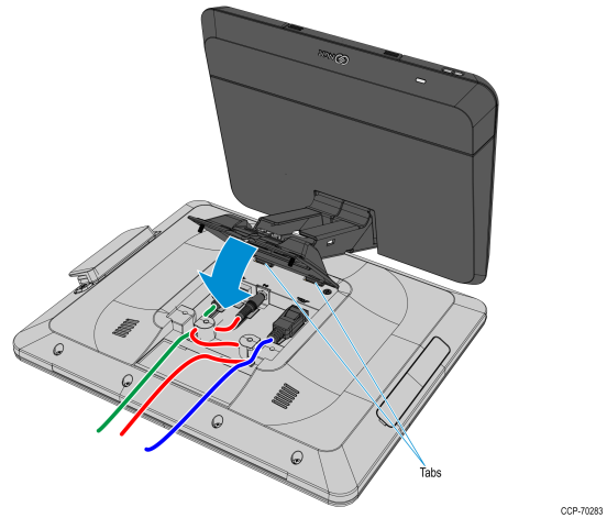
b.Rotate the Base to position the Terminal in the orientation shown below.
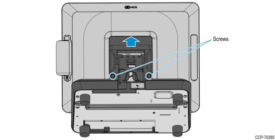
10.Slightly push the Neck and Base assembly forward to properly align its mounting holes with the Head. Secure the Base to the Head with screws (2).
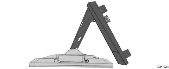
11.Hold the display against the countertop and carefully rotate the Base to the position shown below.
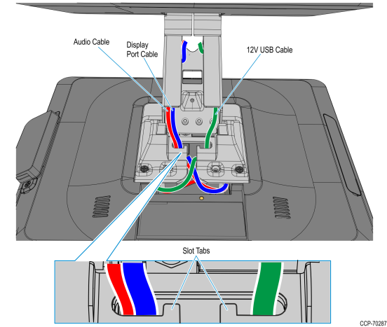
12.Route and secure the Display cables to the Mounting Bracket.
a.Route the Audio Cable to the left slot and make sure it is behind the tab in the slot.
b.Route the Display Port cable to the left slot and make sure it is behind the tab in the slot.
c.Route the USB cable to the right slot and make sure it is behind the tab in the slot.
13.Connect the USB cable to the connector at back of the base.
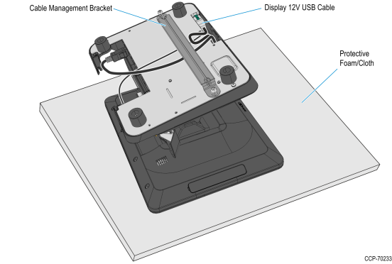
14.Route the Display Port and Audio cables towards the I/O panel at the front of the Base. If a cable management bar is installed, route the cables under the bar.
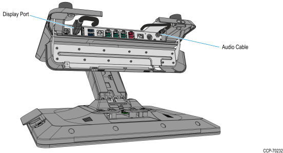
15.Open the I/O cover and connect the cables to the I/O Panel connectors.
a.Connect the Audio Cable to the Audio Out connector on the I/O Panel.
b.Connect the Display Port cable to the Display Port A (Primary Display) connector on the I/O Panel.
16.Mount the the Neck Cover. Hook the Cover to the rear side of the Neck then rotate downward and press the Neck Cover until it latches on to the Neck.